P3 1-2/2023 en
What Does it Mean ...
Lossless Compression Methods
Education Gap

The compression of pixel-based files has become an integral part of today's media landscape - including digital printing. Not least thanks to the jpg format, everyone is familiar with lossy compression methods. The situation is different when it comes to methods that are used in those cases where lossless compression is required, i.e. where it has to be guaranteed that the original file can be restored without color or other errors. Specialist author Jürgen Heuer from the Adolph Kolping Berufskolleg in Münster, Germany, provides information on the basics of such methods.
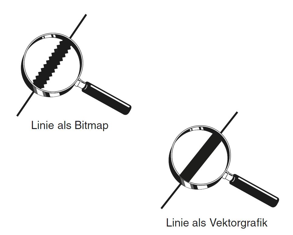
Fig. 1: Pixel vs vector based mapping.
Figures can basically be divided into two groups. On the one hand there are the pixel-based images and on the other hand the so-called vector-oriented images (see Figure 1). Pixel-based images are generally referred to as images, while vector-oriented images are also referred to as illustrations or graphics. For example, if a line is to be displayed, this can pixel-based only be done by stringing together individual pixels. Each pixel describes a defined point of this line. Vector-oriented, the line would be described mathematically only by specifying the start and end points. Today, pixel-based image data is captured using digital cameras or (rarely) converted into digital data using a scanner.
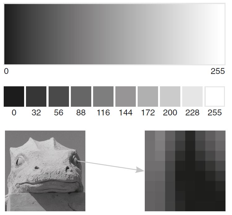
Furthermore, the gray level of a pixel can also be changed during image processing. In the field of digital image processing, a pixel is usually encoded with 8 bits (1 byte). It can thus assume 256 different states (from 0 = black to 255 = white) as shown in Figure 2.
Compression is primarily understood to mean combining the same data. The example below shows a pixel row with 8 pixels (position 1 to 8). Each pixel can assume exactly two different states (in this case, the color depth corresponds to one bit).
To describe this row of pixels (Figure 3), one can proceed as follows:
- Position 1: Black (or value 1)
- Position 2: Black
- Position 3: Black
- Position 4: Black
- Position 5: Black
- Position 6: White (or value 0)
- Position 7: White
- Position 8: White
This information would unambiguously describe the row of pixels shown. If you ask yourself whether this row of pixels cannot be described in a much simpler and, above all, shorter way, it is obvious that the number of black and white pixels can be summarized:
- Position 1 to 5: Black
- Position 6 to 8: White
With the compression method described above (Run Length Encoding) the original row of pixels can be reconstructed without any problems. This is then called lossless compression. The example shows that the possibility of compression is related to the structure of the row of pixels. In the best case, positions 1 to 8 are completely occupied by black or white pixels and the highest compression rates are achieved. In the worst case (black and white pixels are constantly alternating), this method will not achieve any compression at all.
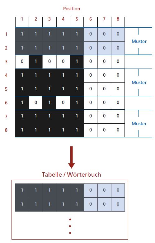
Another approach to lossless compression will be presented at this point for clarification: Figure 4 shows 8 rows of pixels. If you take a closer look at these pixel rows, you will see that rows 1 and 2 are repeated or form a recurring pattern (blue background). This pattern could now be stored in a table (dictionary) and called up when needed.
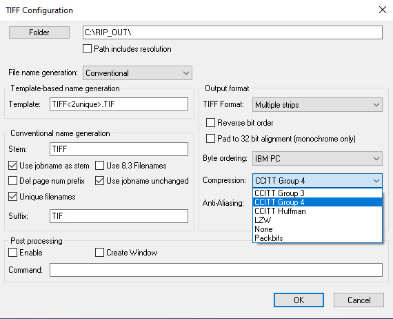
The dictionary builds up dynamically. In the example in Figure 4, first position 1/1 (1) was saved as the first entry, then positions 1+2 (11), then 1+2+3 (111) etc.. Then automatically recurring patterns would develop accordingly and finally be stored. The resulting compression would be many times greater than with run-length coding, since recurring areas from an image file can be saved completely and called up as often as you like. A method that works according to this approach is the LZW method, which is used for TIF files, for example. The TIF output data of a RIP is often compressed using this method, see Figure 5.
Finally, the question can be answered as to how the resulting file size develops when using a lossless compression method, such as the LZW method, if you use an FM raster.

